Array IP8
Array 485
DigiHandset
Rigger handsets
DigiHoist
Array Mini PD-ES
Transform 485
LibraSPLIT

Litec Beam Trolley

Litec DYNAMIC STACK TRACKS
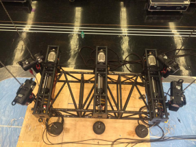
CAPTIVE WINCH S30
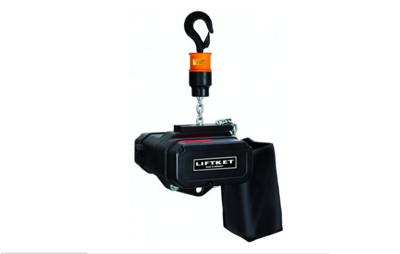
Liftket Chain Hoist Var.Speed

Libracell
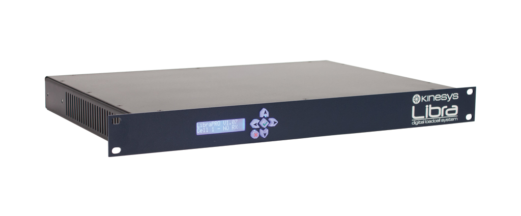
LibraPRO

LibraWATCH

LibraWIFI

Kinesys Elevation1+

Velocity 2

Mentor Series 3

KINESYS K2

Array PD-ES

KINESYS VECTOR
-

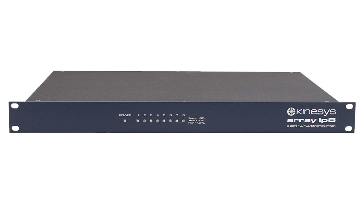
Array IP8
Features 8 port 10/100 BASE-T Ethernet switch Ethercon connectors LED activity lights on the front panel 1U 19” rack mountable case Control Connections 8 x 10/100 BASE-T Ethernet Ethercon 1 x Appliance Inlet/Outlet combination Neutrik powerCON TRUE1 -

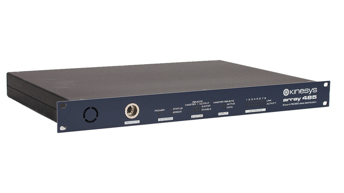
Array 485
Array 485 is a 1 in 8 out RS485 distribution unit for use with Elevation1+. The rear panel features 1 in 8 out XLR7 data connections for outputting RS485 data to Elevation1+ units. The front panel offers link, data and emergency stop status indicators as well as the facility to plug a Rigger remote in for local hoist control. Array 485 Features 1 in 8 out XLR7 RS485 distribution unit Rigger input on front panel for local hoist control Emergency stop LED indicators on front panel 1U 19” rack mountable case, 300mm deep (excluding connectors) Control Connections 8 x XLR7 Output 1 x XLR7 Data Input 1 x Appliance Inlet/Outlet combination Neutrik powerCON TRUE1 -

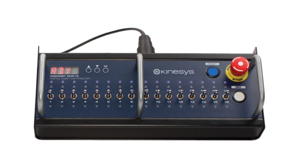
DigiHandset
DigiHandset has channel selection switches, Emergency STOP, GO and RESET buttons and a simple intuitive display to communicate the status of the controller. As soon as the handset is plugged into a DigiHoist it will begin the auto addressing process. A solid blue status indicator above each channel states that a chain hoist is connected and ready to use. The RESET button is used to acknowledge and reset a fault condition within the motor controller, it will flash when action is required. The GO button is used to initiate hoist movement, it will only illuminate if movement is possible. If, for example, the system is in a reset state or if a selected channel has a fault then the GO button will not illuminate. DigiHandset Features The Starburst LED display provides status information about the system in addition to the indicators on the handset Group Halt. A group is defined as any hoists that are active on the system. If a group of hoists are moving and one of them develops a fault, all movement will be stopped Handset menu can be used to modify operating parameters Menu is navigated using three buttons labelled M, Up and Down Direction Indicators: Red ON, down selected Red OFF, no direction selected Red FLASHING, down selected and a down limit has been hit. Same criteria for UP with green arrow Blue status indicators provide information regarding the status of the hoist connected to that channel: ON, a hoist is present on that channel OFF, no hoist detected FLASHING, a problem has been detected with the hoist on that channel -

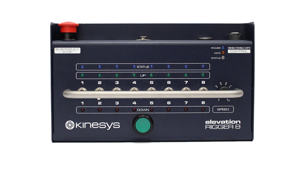
Rigger handsets
Designed to mimic industry-standard handheld controllers the Rigger offers an instantly recognisable method of operation with minimal training required. A Rigger can operate variable speed chain hoists and can be used in place of, or in conjunction with, a computer control system such as Vector or K2. Using the flexible menu system on the Elevation 1+ along with the on-board speed control, the Rigger can be used as a controller for simple set up operations where only basic movements are required. It is not recommended to run shows using a Rigger handset unless allowed by your risk assessment. An Emergency Stop button built into the handset and group halt functionality means that the Rigger provides a safe method of movement for set up purposes. The Rigger will automatically scan and recognise all connected Elevation 1+ units, further enhancing ease of use and operation. Rigger Features The ability to enable and disable the limits using a bypass key Integrated speed control for use with variable speed hoists Positive, direct action toggle switches as well as separate Up, Down and Status indicators provide intuitive and instant feedback Integrated Emergency Stop button, multifunction key switch and a group halt feature ensure the unit can be operated safely and securely A single XLR-7 cable provides the power and data connection required to operate the unit Control Connections XLR7 for power and data 2 x XLR7 on 16 and 24 way Rigger handsets -

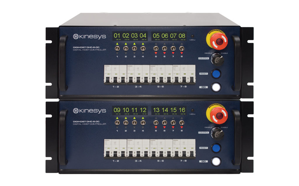
DigiHoist
DigiHoist offers digital communications, limit monitoring, load and position feedback and group halt functionality in a compact package. At the core of the system is a digital communications link that enables multiple units to be daisy chained together. The units will automatically assign channels according to their position in the daisy chain. The high resolution displays offer comprehensive channel feedback including channel number, status and load cell information. The digital link incorporates SIL2 emergency stop connections which eliminate the need for shorting plugs in the system. Safety features include hoist presence indication, limit monitoring, and group halting on fault conditions.* *Not all features are available on Direct Control versions. Low Voltage Control Direct Control Load Cell Input Encoders & Control DigiHoist Features 8 channel capacity Link up to 12 units together (96 channels) Low Voltage and Direct Control versions available Hoist presence and limit detection (low voltage units only). Individual channel feedback Self-healing emergency stop connections 8, 16 and 32 channel handheld remotes Local controls on the front panel Automatic phase reversal correction, with user override facility (override on LV units only) Universal voltage input for worldwide use Mains Input 5-pin 32A Red ‘Ceeform’ type plug to IEC60309 Control Connections Amphenol C16-3 Link In Male 14 + PE Amphenol C16-3 Link Out Female 14 + PE -

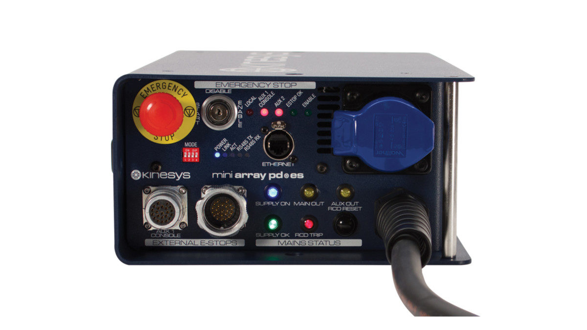
Array Mini PD-ES
This unit provides 32A of emergency stop switched power through two 32A three-phase Ceeform outlets. A single-phase auxiliary outlet is provided for technical use. The three-phase outlets are protected with an adjustable RCD. Along with power and status indicators, the unit includes Transform 485 functionality providing an interface between Vector or K2 and Elevation 1+. Multiple fixing for hook clamps or half couplers allow for a variety of mounting orientations. Array Mini PD-ES Features Power distribution and emergency stop system contained in a compact case Two 32A three-phase Ceeform outlets protected with an adjustable RCD Single phase auxiliary outlet Adjustable RCD Multiple fixing points for hook clamps or half couplers Mains Input/Output 5-pin 32A Red ‘Ceeform’ type plug to IEC60309 2 x 5pin 32A ‘Ceeform’ type socket to IEC60309 1 x 16A ‘Ceeform’ type IEC60309 3 pole connector Control Connections Ethercon for connection to Vector or K2 2 x XLR7 outputs -

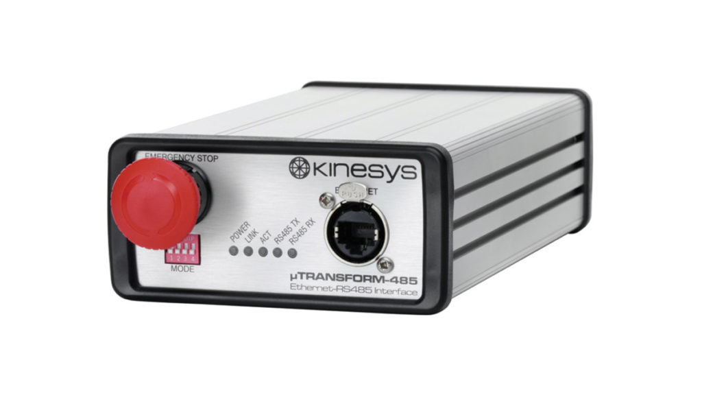
Transform 485
Designed to integrate seamlessly into a motion control system these units allow devices on different networks to communicate. Transform 485 translates between the native Ethernet protocol, outputted by Vector and K2 controllers and the RS485 bus used by the Elevation range via an XLR7. The Transform 485 unit also features an emergency stop button built in, allowing an extra level of emergency stop protection. LED indicators on the front of the Transform 485 give clear indications as to the status of communications and the unit itself. Transform 485 Features Converts Ethernet from K2 or Vector to RS485 used by the Elevation range Built in emergency stop button LED indicators on the front panel Control Connections 2 x XLR7 Outputs -

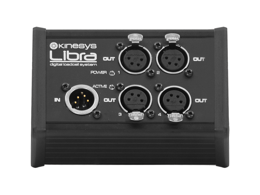
LibraSPLIT
LibraSPLIT permits flexible connection of LibraCELL devices to a single data connector on LibraPRO, LibraBASIC and DigiHoist. The total number of cells connected to LibraSPLIT is restricted by the limitations of the master port or master device. LibraSPLIT is housed in a robust extruded aluminium case and receives low-voltage DC power from the incoming data cable. LibraSPLIT Features Dimensions: 129 x 81 x 47mm (5.1 x 3.2 x 1.9in) (excluding connectors) Weight: 0.27kg (0.6lb) Indicators: Power and Activity Data Input Neutrik XLR4 male Data Output 4 x Neutrik XLR4 female -

Litec Beam Trolley
Speed: 18 o 36mt/min WLL: 600kg -

Litec DYNAMIC STACK TRACKS
Lenght :1m -3M Circle:ø8m -

Liftket Chain Hoist Var.Speed
The new and improved Kinesys converted Elevation Hoist updates the existing Elevation1+ controlled Liftket Chain hoist with an improved Stageket body. Designed with the latest developments in manufacturing in mind, the hoist shares many mechanical parts with our top of the range apexHOIST 500 model, including a new latching chain hook, black chain and 24m height of lift as standard. All Elevation Hoists are fitted with double brakes, four position limit switches, encoder and – in conjunction with LibraCELL – they can reach conformity with many of the worlds most rigorous safety standards. Kinesys Elevation Hoists are available in 280V and 400V. Features Variable speed Liftket, Kinesys converted to be used with the Elevation control system Speed ranges, up to 12m/min or 24m/min depending on model Lifting capacities, from 250kg to 1000kg More configurations available under request Available in the following models in both 208V and 400V versions 250kg D8+ 24m/min 500kg D8+ 12m/min 500kg D8 24m/min 1000kg D8 12m/min Elevation Hoist 250kg D8+ or 500kg D8 Maximum speed = 24m/min Weight of hoist = 41kg Weight of 1m load chain = 1.06kg (7×22 chain) Weight of hoist with 24m (79ft) Height Of Lift (HOL) = 69.62kg Double Brakes Black Chain * Safety Latching Hook Large Delta Plate suspension on hoist body suitable for LibraCELL Overtravel and Ultimate (Emergency) limits * exact colour of chain can vary due to the manufacturing process Elevation Hoist 500kg D8+ or 1000kg D8 Maximum speed = 12m/min Weight of hoist = 41kg Weight of 1m load chain = 1.06kg (7×22 chain) Weight of hoist with 24m (79ft) Height Of Lift (HOL) = 69.62kg Double Brakes Safety Latching Hook Large Delta Plate suspension on hoist body suitable for LibraCELL Overtravel and Ultimate (Emergency) limits -

Libracell
LibraCELL is a load measuring shackle which, when combined with the other elements of the Libra system, produces accurate, real time load information. LibraCELL is designed for indoor use and is not waterproof. The load cell itself features the Libra shackle pin, which is designed to work exclusively with the world-wide recognised Crosby safety bow shackle. This innovative design means there is no loss of headroom as the load cell is built right into the shackle, a direct replacement for the famous ‘red pin’. The Libra shackle maintains a safety factor of 5:1 up to the full rated load stamped on the side of the bow. Built into the load cell is a highly visible LED display allowing users to view the live load as well as input a tare value and switch between kg and lbs, all via an easy to use menu system. Features 3.25TE (5/8) and 4.75TE (3/4) capacity at 5:1 safety factor 1.62T (5/8) and 2.37T (3/4) capacity at 10:1 safety factor On board load readout in lbs or kg Shackle design means no loss of headroom Built in menu for setting tare and other options Control Connections XLR4 Power and Data Input XLR4 Power and Data Output 4-pin Binder LibraCELL to Elevation 1+ Connector -

LibraPRO
The LibraPRO features four XLR4 outputs allowing up to 100 loadcells to be monitored. It also features four programmable relay outputs and Ethernet connectivity. Integration is at the heart of the LibraPRO, multiple LibraCELL outputs and USB and Ethernet connectivity make this the core of a Libra system. LibraPRO relay outputs can be utilised to trigger alarms or beacons to warn of underload or overload situations. When LibraPRO is used with LibraWATCH it can unleash its full potential. By downloading the free multiplatform software application LibraWATCH onto a computer, smartphone or tablet device you have the option of viewing load data in tabular, graphical or plan form through a user friendly interface. LibraWIFI allows LibraWATCH to connect wirelessly whereby load data can be monitored on the go through multiple devices, thereby allowing key parameters to be edited remotely. This gives all personnel a complete overview of the safety of any rigging installation. LibraVIEW can also connect to LibraPRO via its Ethernet or USB interface. In order to work with LibraWATCH, LibraPRO needs to be running V2.14 firmware or later. LibraPRO Features USB and Ethernet connection for LibraVIEW Connect up to 100 loadcells Ethernet connection for LibraWATCH Programmable relay outputs 4 x XLR4 data connections 1U 19” rack mounting case Control Connections 4 x XLR4 LibraCELL Outputs 1 x Ethernet (Ethercon) 1 x USB (Type B) 2 x Mains Switched Relay Outputs 2 x Volt Free Relay Outputs -

LibraWATCH
LibraWATCH is a portable, user-friendly and powerful load monitoring software application that is an integral part of the Libra range; LibraCELL, LibraPRO and LibraWIFI. It is a multi-platform software program which can be used on any computer, tablet or smartphone device. It gives the option of viewing load data in tabular, graphical or plan form through a user-friendly interface, which can be deployed on many different products, while still maintaining a consistent, universal look. Overload and underload alarms and warnings can be communicated through multiple devices simultaneously. Many users can therefore maintain a complete overview of the load status and via a PIN number have access to edit key parameters remotely. In order to transmit the load data wirelessly the system uses LibraWIFI. This wireless node comes with a built in Firewall to allow only Kinesys data into the Libra system which ensures a fast, secure and safe network. Accessible to all, the connection is compatible with Windows, Mac, Android and iOS. The use of LibraWATCH at a live event can transform the way load data is communicated as it enables freedom and mobility for all the technical staff. This element of the complete Libra range is a must have for the entertainment market today. Software Features Graph View Visualise live loads in bargraph form as well as overload, underload and maximum and minimum values. This is the real time dynamic visualisation of each LibraCELL connected to. Different bar colours shows the LibraCELL’s status and give immediate visual feedback of underloads, overloads, load fluctuation range and load warnings. Group functionality allows users to allocate individual cells into a group and to see the total weight of a grid, a truss or a P.A. Load Table View Visualise individual loads and groups in a grid table format. This is the working load table, essential for load calculation and load verification. It allows you to create groups simply by selecting individual cells and saving them with a specific name. LibraCELL groups can be visualised both in Table and Graph view. LibraWATCH generated load table reports can be saved locally or sent by email using your portable device. Users can also save their shows for future recall. Plan View View live loads positioned over a plan view of the installation. Install LibraWATCH on a PC or a Mac, drag and drop an image of a rigging plot or a show plan on to the device and save it. When you connect LibraPRO to your computer it will upload the show file which can then be broadcast via LibraWIFI onto your portable device and be visualised with LibraWATCH. Plan View also works without background images and it shows LibraCELL positions based on parameters set for each individual cell. Setting Parameters Allows the adjustment of various cell parameters – address, name, overload and underload. Optionally protected by a PIN number. LibraWATCH system settings permit you to reset load fluctuation range, discover LibraCELL’s, set trigger limits and set up individual relay actions. It is possible to allocate X and Y positioning coordinates for each individual LibraCELL to be viewed in Plan View. The Options screen permits you to select a language, to choose units of measurement and to define alerts. To access this free software application, LibraWATCH can be downloaded from a range of sources for various devices: iOS devices – Apple Store For Windows machines (Standalone installer) – Download For Mac Machines (Google Chrome extension) – Download LibraWATCH Features Free download iOS, Android, Windows, Linux and Mac support View LibraCELL data anywhere via Wifi or Ethernet Multiple devices can be connected simultaneously Set overload and underload alarms View data as a table, a graph or on a plan Minimum System Requirements Free download iOS, Android, Windows, Linux and Mac support View LibraCELL data anywhere via Wifi or Ethernet Multiple devices can be connected simultaneously Set overload and underload alarms View data as a table, a graph or on a plan -

LibraWIFI
A key advantage of LibraWIFI is its unique design, perfect for using at any live entertainment event. The aerial can be easily mounted onto any truss, maximising the chances of generating the best signal without any limitations. A built in Firewall permits only Kinesys data into the Libra network which allows load data to be communicated in a fast, secure and safe way. LibraWIFI is compatible with all Kinesys systems and can be plugged into a DigiHoist to broadcast LibraCELL data without the need of a LibraPRO. LibraPRO and DigiHoist can be connected to an Ethernet network thereby allowing LibraWIFI to have access to all the load data in the system. Wireless networks can be unpredictable under live show conditions – Kinesys recommends the use of a wired network connection whenever possible if load monitoring is required during a performance. LibraWIFI Features Allows LibraCELL data to be broadcast wirelessly Use with LibraWATCH Built in Firewall ensures a faster, safer, more secure load data network Ethernet Connection An Ethernet connection (PoE) from LibraPRO provides power and data to LibraWIFI Supports IEEE 802.11 b/g/n (2.4 GHz) IEEE 802.11 a/n (5 GHz) option available -

Kinesys Elevation1+
The Elevation1+ removes the need for large quantities of cabling and permits a number of motors and controllers to be supplied by single power and data cables. Elevation1+ together with customised versions of the most popular models of chain hoist, such as Lodestar, Liftket and GIS, represents the most flexible and reliable variable speed ‘open system’ available in the market. Easy to install, simple to configure and with an ergonomic and compact design, it has the ability to ramp start, ramp stop, position and vary the speed of a chain hoist for maximum creative effect. With the addition of a simple adapter cable, the converted motors can be used as standard fixed speed chain hoists allowing maximum flexibility of motor use. The Elevation1+ can be controlled by K2 or Vector software packages and interfaces with other Kinesys products for a totally integrated show control system. Elevation1+ is available in both US and European voltage variants, with multiple fixings for hook clamps or half couplers which allow for a variety of mounting orientations. Elevation 1+ Features 32A mains input and output connections all ‘daisy-chain’ operation Robust multipin connector for hoist connection – includes motor, brake, limit switch and encoder connections Remote control input allows full variable speed operation using a Kinesys pendant LED display, intuitive menu system and rugged manual control buttons allow for easy setup Hoist Connection 5pin 32A ‘Ceeform’ type socket to IEC60309 Control Connections 7-pin male XLR connector with female link out Hoist Connection 8+24-pin ‘Harting’ connector -

Velocity 2
The unit incorporates its own position controller allowing it to operate stand-alone or as part of a larger networked system. Velocity 2 offers unique features and performance in a very compact package. Engineered to deliver power and performance to high-end automation machinery, the highly flexible Velocity 2 offers capacities from 0.75kW to 110kW in a variety of sizes ranging from 4U, to flightcased drives, including custom cabinets and multiple drive systems. In most applications Velocity 2 offers a complete solution without the need for external ‘regen’ units or ‘braking resistors’. Instead, internal brake resistors and temperature controlled forced air cooling for quiet operation at 100% duty cycle are included. All drive and interface parameters may be accessed through the incorporated colour touchscreen display, which provides detailed diagnostic information and performance feedback. The Velocity 2 drive also includes manual controls for quick and intuitive local control when required. The Velocity 2 drive can be controlled by K2 or Vector software packages and interfaces with other Kinesys products for a totally integrated show control system. Velocity 2 Features SIL3 safety technology is available as a factory fitted option, offering functionality Configurable for open and closed loop operation of ac induction, linear and servo motors Integral position controller creates a self-contained motion control system Multiple control options from manual controls and pendants to a fully featured computer interface Compact design without sacrificing high power output options Rugged case design for physically demanding touring environments Compatible with K2 and Vector software Interfaces with multiple types of incremental and absolute encoders, load monitoring and other sensors -

Mentor Series 3
Mentor products provide the key interface between Kinesys’ different product ranges, allowing the emergency stop systems built into EVO, Velocity 2, Elevation, and DigiHoist systems to work together simply and easily. Combined with Kinesys’ Mentor safety controllers, EVO can form part of a complete SIL3 emergency stop system. Mentor Series 3 Features SIL3 Emergency Stop Front panel diagnostic Intelligent E-STOP monitoring Connections Options E-STOP + DMH 10-Pin MIL connector in 2x Ethernet ports for diagnostic purposes Neutrik powerCON TRUE 1 (Power In/Out) Neutrik Ethercon for EVO 19-Pin MIL for advanced devices (Velocity 2) -

KINESYS K2
K2 Console K2 is available as a Console (with a PC built in) as well as a standalone piece of software. The Console provides a self-contained hardware solution (custom built by Kinesys) which includes a PC optimised to run K2, delivering the best possible user experience. The Console allows for faster programming and easier operation with dedicated buttons and playbacks for controlling K2. An Emergency Stop button and Dead Man’s Handle are also built into the Console for connection into an emergency stop system, including the Array PD-ES. K2 Software The programming and playback environments display real moving objects as realistic graphical representations. These are positioned in a 3D space in the correct proportions and relation to the stage, set and other items as well as other moving objects. All these graphical items can be created in industry standard CAD packages and imported directly into K2. Programming then becomes very simple, with manipulation of the moving objects as straightforward as click-and-drag. The ability to move objects in real world axes, X, Y, Z, pitch, tilt and rotate makes programming very intuitive with K2 shielding the user from the complex multi-dimensional calculations required and instead presenting them with easy to use programming parameters. User programmable limits and clamps allow envelopes of motion to be easily constructed around objects. When combined with numerous other safety features and extensive feedback to the user, the programmer is in complete control of the devices being used. K2 is not just limited to winches and chain hoists – any number of devices can be connected to this powerful and flexible system. Personality files make integrating new mechanical devices into the system very straightforward. K2 includes the ability to output positional information to media servers, allowing for a great deal of creative freedom and flexibility when using motion and video together. Licensing A free demo version of K2 is available for download. This version of the software is fully featured, but will not output any commands to carry out movement. A full K2 license can be purchased by contacting us at info@kinesys.co.uk. K2 This ground breaking product combines the best aspects of existing programming methodologies with some stunning new concepts. K2 is Kinesys’ motion control console and employs a intuitive approach to automation programming. The operator uses ‘click and drag’ to move objects on the screen within a 3D world rather than typing positions into a table. This gives instant feedback as to the object’s position in relation to other moving items. Features Graphical 3D graphical programming environment “Look-ahead” collision detection system 3D world and object import from CAD Offline working for cue programming and visualisation Unlimited channel and cue capacity Status monitoring of all Kinesys drives -

Array PD-ES
This 6U 19″ rack module provides 125A of emergency stop switched power through four 32A three-phase Ceeform outlets. All three-phase outlets are protected with an adjustable RCD. A single-phase auxiliary outlet is provided along with dual XLR7 data outputs for connection to Elevation1+ controllers. The unit includes Transform 485 functionality providing an interface between Vector or K2 and Elevation 1+. The front panel features an integrated Emergency Stop button, status indicators, individual MCBs for each Ceeform outlet and an adjustable RCD. ‘Power Present’ status indicators are provided on both front and back panels. Array PD-ES Features Power distribution and emergency stop system contained in a 6U 19″ rack enclosure Single-phase auxiliary outlet 4 x 32A three-phase individually switched Ceeform outlets Adjustable RCD Integrated Emergency Stop Button Mains Input/Output Powerlock or CamLok E1016 type single-pole connectors with through outlets 4 x 32A “Ceeform” type IEC60309 5-pole connectors 1 X 16A “Ceeform” type IEC60309 3-pole connector 1 x outlet suitable for local territory e.g. Schuko/Edison Control Connections Ethercon for connection to Vector or K2 2 x XLR7 outputs -

KINESYS VECTOR
Vector software allows cues to be built and run with a variety of linking options. The amount of cues that can be built and channels that can be controlled are limited only by your imagination. Creating and Editing Cues Vector has a wealth of cue creation and editing features designed to allow rapid entry and programming of cues. Advanced linking features allow complex cue sequences to be easily constructed while maintaining maximum flexibility over the overall operation of the devices in motion. Four playbacks allow cues to be run simultaneously and manual running features make all aspects of movement easy and safe. Vector runs on compatible Windows computers with the option of a USB keypad for faster editing and operation. Integrates with other Kinesys products Vector’s full integration with all Kinesys controllers also ensures that maximum feedback is available to the operator for ease of system monitoring. Comprehensive channel settings allow remote configuration of the drives and controllers in the system. Safety and Security Three levels of user login allow different levels of access to be granted to ensure the safety and security of the system is maintained. For more complex moves a ‘Dead Man’s Handle’ can be assigned on a channel by channel basis as well as group halt and error windowing to prevent members of a group from moving out of synchronisation. Licensing A free demo version of Vector is available for Download. This version of the software is fully featured, but will not output any commands to carry out movement. A full Vector license can be purchased by contacting us at info@kinesys.co.uk. Vector Features Integrates seamlessly with other Kinesys hardware to provide easy setup, operation, real time feedback and remote configuration Advanced linking and timing features allow complex cues to be built and run simultaneously with four colour coded playbacks Safety features include three levels of login access, ‘Dead Man’s Handle’ on a channel by channel basis, group halting and error windowing Manual mode allows ease of use during installation or maintenance periods without the need for cues to be written


